Connect a MatrixPortal S3 to a 64×32 LED Panel
This guide is for the physical job: taking an Adafruit MatrixPortal S3 and a 64×32 HUB75 RGB matrix panel and wiring them together. It is adapted directly from the illustrated ThemeParkWaits Build Your Own and Assembly Guide.
Everything plugs together. There is no soldering, and an enclosure is optional.
What you need
- Adafruit MatrixPortal S3 (product #5778).
- 64×32 RGB LED matrix panel, 3 mm pitch (P3), with a HUB75 interface. The panel usually includes the gray HUB75 ribbon cable and red/black 5 V power lead.
- 5 V USB-C power supply, rated for at least 3 A.
- USB-C cable.
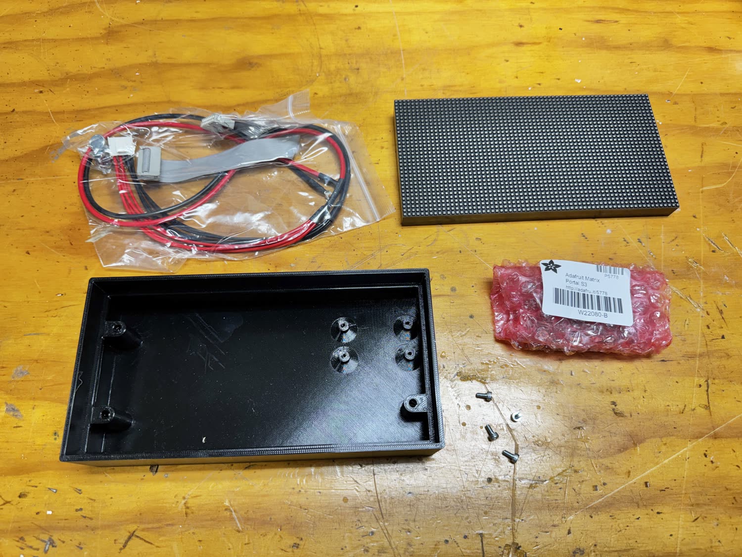
Disconnect USB power before wiring
Do not attach or remove the ribbon cable or power leads while the MatrixPortal is powered.
Hook up the board and panel
1. Fit the HUB75 connector to the MatrixPortal
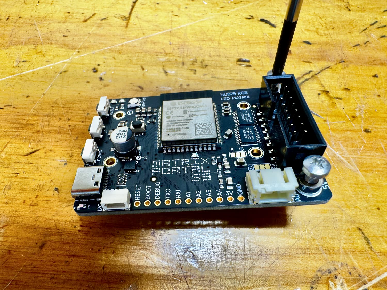
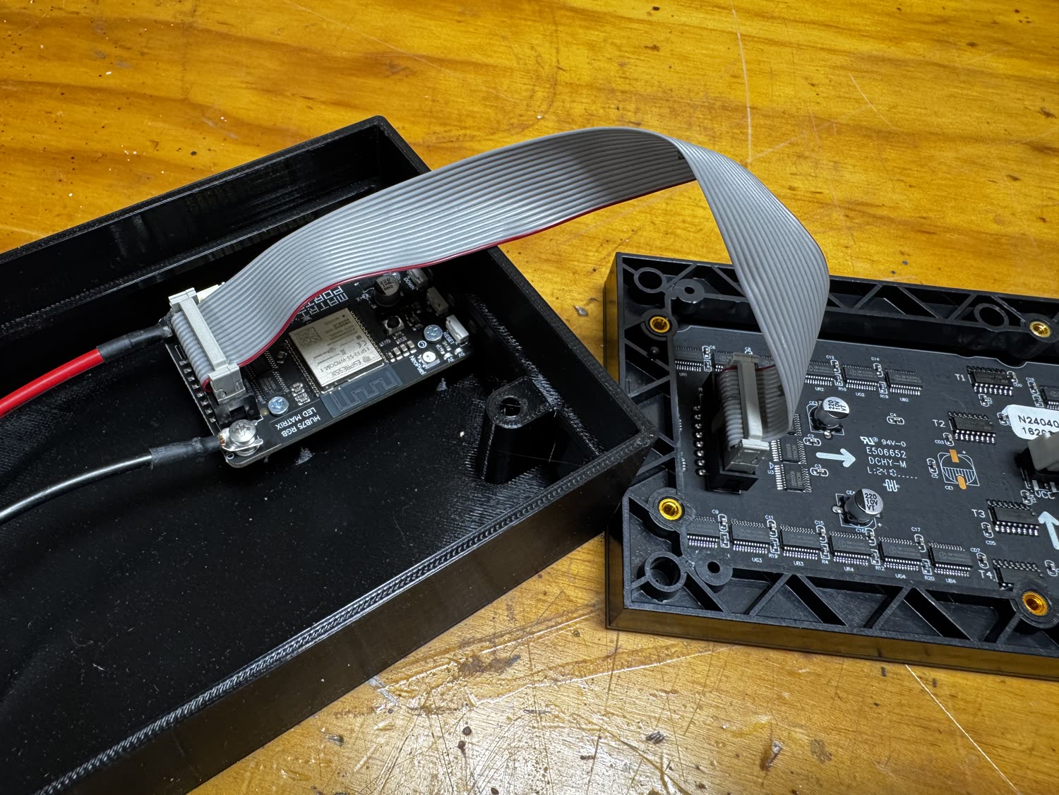
Seat the black HUB75 ribbon-cable header firmly on the MatrixPortal's two rows of pins. The connector is keyed and only fits in the correct orientation. Press on the plastic housing until it is fully seated and level.
2. Connect the ribbon and power leads at the MatrixPortal
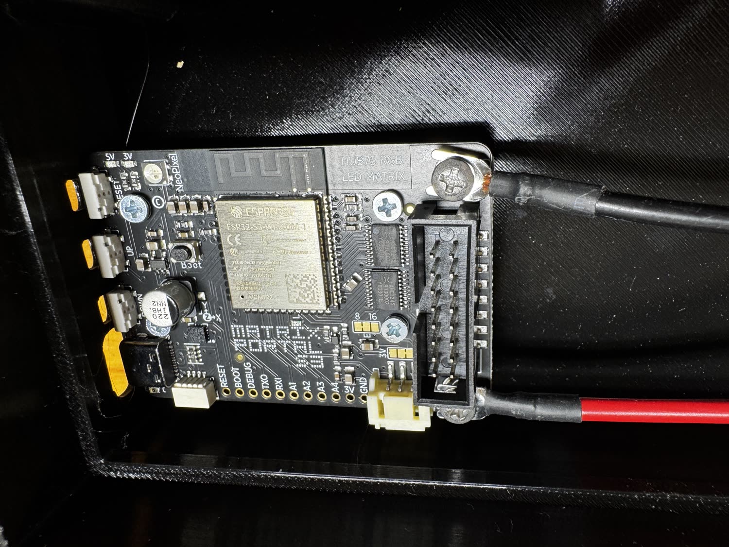
Plug one end of the gray HUB75 ribbon cable into the connector you just fitted. Its keyed plug prevents it from being reversed.
Attach the panel's forked power leads to the MatrixPortal screw terminals:
- Red → 5V
- Black → GND
Loosen each terminal screw, slide the matching fork underneath, then tighten it securely. Route both cables toward the LED panel without pulling on the board.
3. Connect both cables to the LED panel
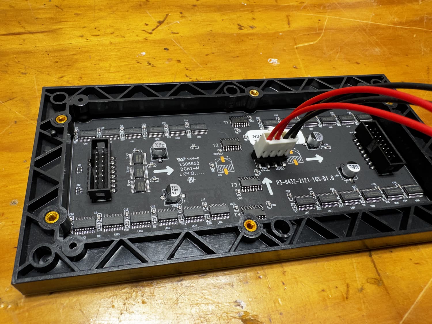
On the back of the panel, plug the ribbon cable into the HUB75 input, not the
output. On the panel pictured here, the input is the left-hand HUB75 socket at
the tail of the printed arrows. Follow the IN/OUT labels or arrows on your
panel if its layout differs.
Press the white power plug into the panel's power socket, matching the red wires to VCC and the black wires to GND.
4. Inspect the hookup, then connect USB-C power
Before applying power, check all four connections:
- The HUB75 header is fully seated on the MatrixPortal.
- The ribbon cable is keyed at both ends and uses the panel's input.
- Red runs from MatrixPortal 5V to panel VCC.
- Black runs from MatrixPortal GND to panel GND.
Connect the 5 V, 3 A-or-better supply to the MatrixPortal's USB-C port. That single connection powers both the controller and the panel.
What comes next
The hardware is now assembled. A new or blank MatrixPortal will not display a ScrollKit app until CircuitPython, the app, ScrollKit, and the required Adafruit libraries are installed. Continue with Deploying to hardware.
Panel stays blank after software is installed
Disconnect USB power, reseat the ribbon at both ends, confirm it is in the panel's input socket, and recheck red-to-5V/VCC and black-to-GND before powering it again.